 プレート電圧がスクリーングリッド電圧よりも低くなると、プレート電流が減少する分、スクリーングリッド電流は増加する。それならスクリーングリッド電流とプレート電流を一緒に出力することで、歪みが減り、効率が高まる。特に低いプレート電圧で動作するOTLアンプでは効果的。
Evolve Power Amplifiers * Links
Ip +Isg Output / Hybrid / Output Transformer Less
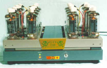
EL509 ステレオパワーアンプ
MJ無線と実験 1995年10月号 に発表
 プレート電圧がスクリーングリッド電圧よりも低くなると、プレート電流が減少する分、スクリーングリッド電流は増加する。それならスクリーングリッド電流とプレート電流を一緒に出力することで、歪みが減り、効率が高まる。特に低いプレート電圧で動作するOTLアンプでは効果的。
図面にはPDFファイルを使用しています。
PDFファイルを表示するために必要なアクロバットリーダーを、アドビシステムズ社が無償で提供していますので、詳しくはここを
>> ![]() << クリックしてください。
<< クリックしてください。
PDFファイルを表示後はブラウザの[戻る]で本文に戻れます。

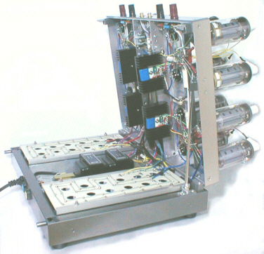
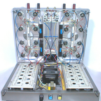

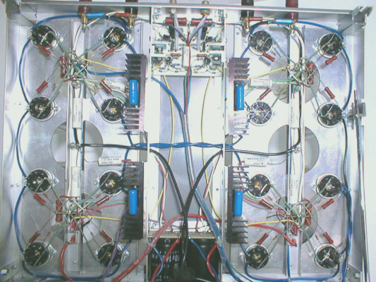
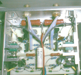
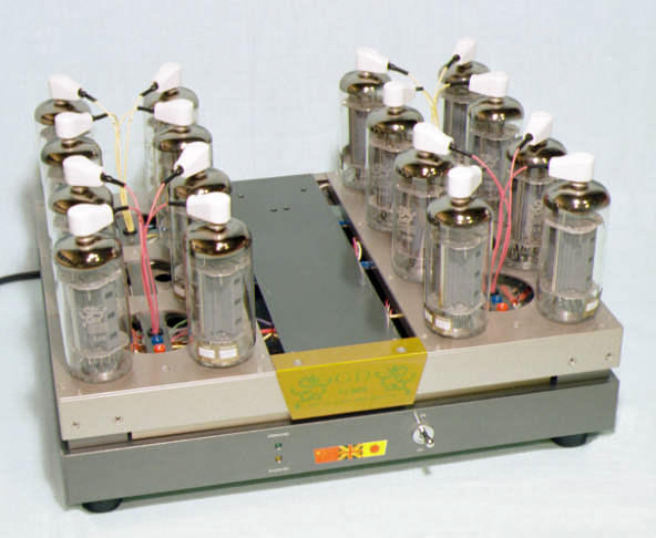
File list
| 1z02.pdf | 137kB |
Data sheet of TANGO insulation transformer. | |
16kB |
Output wave form of 10kHz square wave in 8Ω load. | ||
16kB |
Output wave form of 10kHz square wave in 8Ω and 0.1μF parallel load. | ||
17kB |
Output wave form of 10kHz square wave in 8Ω and 0.47μF parallel load. | ||
| AN6781_1-5.pdf | 109kB |
Data sheet of timer IC AN6781. | |
39kB |
Background image on title page. |
||
17kB |
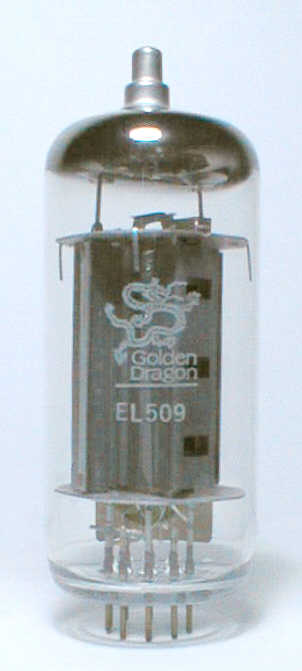
Externals photograph of EL509. |
||
| el509.pdf | 103kB |
Data sheet of EL509. | |
25kB |
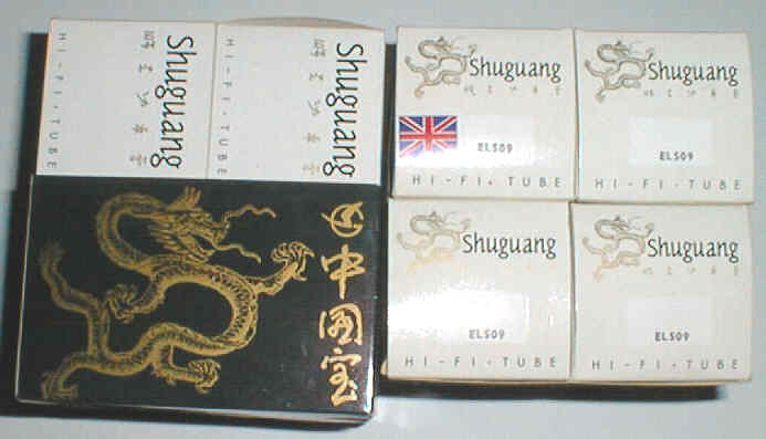
Package photograph of EL509. |
||
4kB |
General connection. |
||
40kB |
Design of chassis. |
||
35kB |
Design of chassis. |
||
55kB |
Arrangement in chassis. |
||
61kB |
Arrangement in upper chassis. |
||
42kB |
Arrangement in lower chassis. |
||
29kB |
Wiring for heater. |
||
25kB |
Wiring for heater. |
||
73kB |
Wiring for output stage. |
||
64kB |
Wiring for output stage. |
||
56kB |
Wiring for drive stage board. |
||
61kB |
Wiring for drive stage board. |
||
10kB |
fig1-4 |
||
10kB |
Wiring for screen grid voltage regulator board. |
||
13kB |
Wiring for screen grid voltage regulator board. |
||
19kB |
Wiring for timer board. |
||
29kB |
Wiring for timer board. |
||
4kB |
Correction of high region distortion. |
||
7kB |
Correction of high region distortion. |
||
11kB |
Frequency response characteristic. |
||
7kB |
Frequency response characteristic. |
||
14kB |
Distortion rate characteristic. |
||
7kB |
Distortion rate characteristic. |
||
7kB |
Ep-Ip characteristic (EL-509). |
||
15kB |
Output impedance characteristic. |
||
7kB |
Output impedance characteristic. |
||
4kB |
Triode connection. |
||
5kB |
Esg is constant.,Ip+Isg output. |
||
4kB |
Design of EL509 4 parallel SEPP. |
||
9kB |
Design of EL509 4 parallel SEPP. |
||
23kB |
Basic circuit. |
||
13kB |
Basic circuit. |
||
24kB |
The entire composition. |
||
17kB |
The entire composition. |
||
61kB |
Schematic of this amp (each channel part). |
||
37kB |
Schematic of this amp (each channel part). |
||
47kB |
Schematic of this amp (both channel part). |
||
24kB |
Schematic of this amp (Both channels common parts). |
||
81kB |
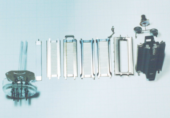
Internal structure of EL509. |
||
124kB |
Chassis of power supply side. |
||
177kB |
Chassis of amplifier side. |
||
76kB |
Drive stage board. |
||
33kB |
On the front. |
||
36kB |
Upper right. |
||
66kB |
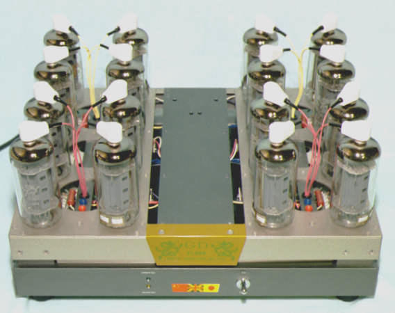
Front view. |
||
45kB |
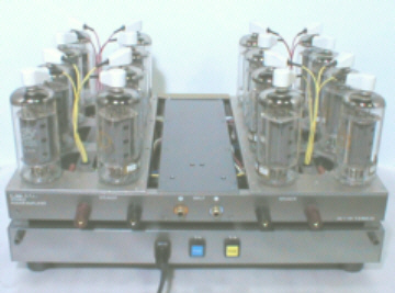
Rear view. | ||
44kB |
Output wave form of 10kHz square wave in 8Ω load. | ||
43kB |
Output wave form of 10kHz square wave in 8Ω and 0.47μF parallel load. | ||
119kB |
Chassis of half opening. |
||
24kB |
Chassis of half opening 2. |
||
77kB |
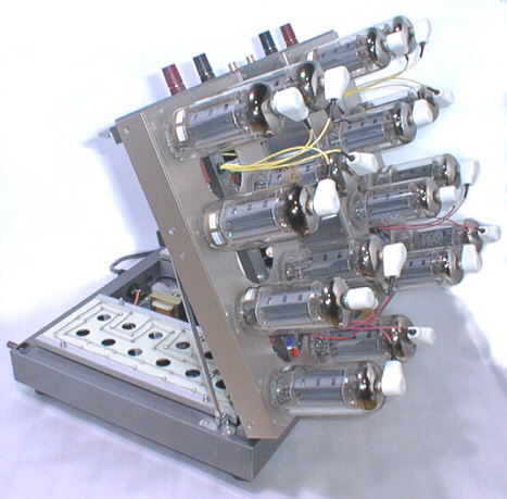
Chassis of opening, after the diagonal view. |
||
111kB |
Inside of chassis. |
||
25kB |
Content page. |
||
30kB |
Title page. |
最終更新日: 2000/08/01 21:39:07 +0900