Super triode connection version 4
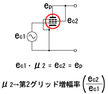
図1に示す5極管のプレートにスクリーングリッドを接続した3極管接続の動作は、スクリーングリッドがプレート電圧を制御しているために、プレート電圧はスクリーングリッド電圧に等しくなっていると解釈できます。
カソードとコントロールグリッドとスクリーングリッドの部分が一個の3極管を形成しているために、この部分で電圧増幅が行われ、プレートは電流増幅だけをしていると見なせます。
そこで、これと同じ動作を他の回路接続できないかと考えました。
Because the circuit is interesting, I introduce the content here though I have not manufactured the amplifier which adopts this method yet.
It can be interpreted that the voltage of the plate is equal to the screen grid voltage because the screen grid controls the voltage of the plate as for the operation of the triode connection which connects the screen grid with the plate of the pentode shown in Figure 1.
The voltage amplification can be done in this part because the cathode control grid screen grid part forms one triode, and the plate be considered to do only the current amplification.
Then, I thought whether the same operation as this was able to be connected in other circuits.
Figure 1:Triode connection of pentode
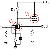
The output voltage is not fed back to the plate of V1 though the voltage amplification and the current amplification are allotted as for Figure 2 because the input signal voltage is amplified with V1 and it is output by the cathode follow of V2.
Figure 2:Cathode follow output
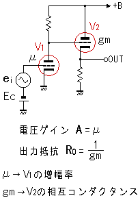
Figure 3:SRPP circuit
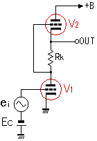
図3のSRPPでは、V1が電圧増幅だけをするには、RKは定電流性でなければならないし、出力電圧がV1のプレートに伝わるには、RKは定電圧性でなければならないため矛盾を生じます。
In SRPP of Figure 3.
RK should be a constant current for V1 to do only the
voltage amplification, and contradiction is caused because RK should be a
constant voltage to spread the output voltage to the plate of V1.
この回路の動作はV2がV3を制御して、出力電圧をV1のプレート電圧と等しくします。
出力抵抗はおよそRo=rp/Rp gmとなります。
電圧増幅特性はV1の3極管特性に依存します。
Then, I
began to think about the super triode connection version 4 shown in Figure 4.
The operation of this circuit controls V3 by V2, and equates
the output voltage with the voltage of the plate of V1.
The output resistance becomes about Ro=rp/Rp gm.
The voltage amplification characteristic depends on the triode characteristic of V1.
Figure 4:Super triode connection version 4
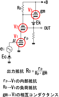
Figure 5:Application of super triode connection version 4
drive amplifier
stabilization power supply
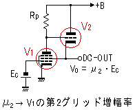
電圧ゲインがあり、SRPPやカソードフォロワーを凌ぐ低い出力抵抗であり、歪みが少ないので、シンプルで高性能なドライブアンプとして使えます。
また、出力の定電圧特性を利用して、安定化電源としても応用できます。
The
circuit which replaces V1 and V2 with one pentode is simple
as shown in Figure 5 and practicable.
There is a voltage gain. It is low output resistance to surpass SRPP and the cathode
follow. The distortion is a little. Therefore, this can be used as a simple, efficient
drive amplifier.
Moreover, this can be applied as a stabilization power supply by using the constant
voltage characteristic of the output.